

There are a tremendous amount of parts that need to go together to create a working solar car. While building a chassis and putting on bodywork are important, a huge aspect of the work is what goes on inside the car. All of the electrical systems need to be designed to be efficient and manage the solar panels and battery. One part of the electrical system is all of the circuits that are part of the car. Over the past few months we have been working hard to try and complete all of the electrical systems

Above: Part of our electrical schematic, including the interconnection board and part of the Arduino.
One major part of our electrical system is the “interconnection board” where many of our systems run through. It also holds our Arduino Mega which collects data like the motor temperature and battery voltage from different parts of the car. We created an electrical schematic and then designed the layout for the board. After finishing up our design, we spent many hours carefully soldering parts and wires onto the board. After testing it we had to do some troubleshooting to find some mistakes, but we were able to fix all of the errors. Our next step is to get a custom circuit board to make the components neater and more resistant to vibrations during the race. Doing this will ensure that no wires disconnect or short out from the interconnection board.

Above: The front side of our interconnection board mounted on the car.
Circuits can be extremely complex which is why it is always good to start with the basics. For new and returning team members who have not previously worked with circuits, it is good to start with small projects and then work your way up. Tinkercad, a program which allows you to build small circuits and grow your programming skills, is a great resource to start with.
Tinkercad has a few tutorials that can be used to help learn about circuits and how to use Tinkercad. To find them from the homepage of Tinkercad, click on “learn” in the top right and then change it from 3D to Circuits on the upper left side of your screen. Here you can find the four tutorials about circuits. To create a basic circuit of a light, you can go back to the homepage and change it to circuits. Then you create a new circuit and start by placing a battery in your workspace. You can find the 9V battery in the basic components section on the right. Next, you can place a push button and connect a wire between the positive terminal of the battery to the 1a connection on the pushbutton. You can create a wire by clicking on the red wire coming out of the battery and then clicking on the pushbutton where you want it to end. When you have done this, add a resistor next to the pushbutton and connect the pushbutton (2a) to the resistor with a wire. Then add an LED to the workspace and connect a wire from the other end of the resistor to the light. Make sure it goes to the anode connector and not the cathode. Connect the light and the battery and click start simulation which should be in the top right. Now if you click on the pushbutton your light should light up. To create more complex circuits you can use the same techniques.
One of the major parts of our electrical system are relays. We use relays to control the flow of electricity and to make sure it only flows to certain areas when we would like it to. Relay are electronically controlled switches which use electromagnetic coils to control the contacts. In our car we use relays for both low and high voltage electricity and to control our emergency shut-off buttons. This allows us to use low-voltage electricity to control the high-voltage electricity. You can add relays in Tinkercad as well.
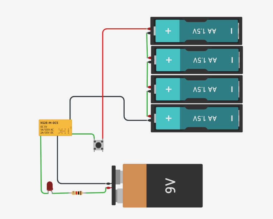

In the example on the left, the light is connected to the “normally open” pin and will turn on when you push the button. When you push the button, electricity runs through the coil in the relay which changes the position of the contact in the relay which allows electricity to flow between the 9V battery and the LED. In the example on the right, the LED will normally be on and will turn off when you push the button. In the two examples above, the lights were either connected to the normally open or normally closed contacts. When you run the electricity through the electromagnet it switches the contact. This causes the circuit which was originally open to be closed and the circuit which was originally closed to be open.
Circuits are extremely important to our car and need to be understood by the entire team. We have spent a significant portion of our time during the past few months working on designing and building all of the circuits and electronics in our car. Everyone has spent time learning how they work and what they can do and Tinkercad is a great resource for that. Without circuits our car would not function and we would not get any data. We will continue to spend time adding more and revising our current circuit and electronics on the car until the competition in July.